Realiza algunos cambios en el entorno mundial
La máquina que ha comprado le reportará beneficios, pero también cambiará indirectamente el medio ambiente mundial y dará a los residuos plásticos una oportunidad de aprovechamiento.

Realiza algunos cambios en el entorno mundial
Last year, I spent three days troubleshooting a recycling extruder that kept producing pellets with tiny bubbles inside. The client had replaced the screw, swapped the die, and even changed resin suppliers. Turned out the problem was a cracked breaker plate nobody had inspected in two years. Every single part of a plastic extruder machine has a job, and when one fails silently, it drags the whole line down. This guide breaks down each component of a plastic extruder machine, explains exactly what it does, and shows you how all the pieces work together to produce consistent, high-quality output in 2026 production environments.
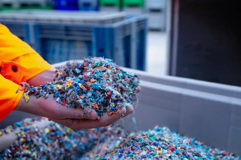
A plastic extruder machine is, at its core, a giant heated meat grinder for polymers. You feed solid plastic in one end—pellets, flakes, regrinds, whatever your feedstock looks like—and out the other end comes a continuous, molten stream shaped into pipes, sheets, films, profiles, or pellets ready for downstream use.
The basic principle hasn’t changed in decades: a rotating screw pushes material through a heated barrel, melts it through a combination of friction and external heat, and forces the homogeneous melt through a die that gives it shape. Simple concept. But the devil is absolutely in the details of each component.
Why should you care about individual parts? Because I’ve watched operators lose $15,000+ in scrap material over a single week because they didn’t understand how a worn metering zone was affecting their melt pressure. In 2026, with recycled resin feedstocks becoming the norm rather than the exception, understanding your extruder’s anatomy isn’t optional—it’s the difference between profitable production and expensive headaches.
Modern extruders used in plastic recycling operations face tougher demands than ever. Contaminated feedstock, mixed polymer batches, and tighter quality specs for recycled pellets all put more stress on every component. So let’s walk through each part, starting where the material enters the machine.
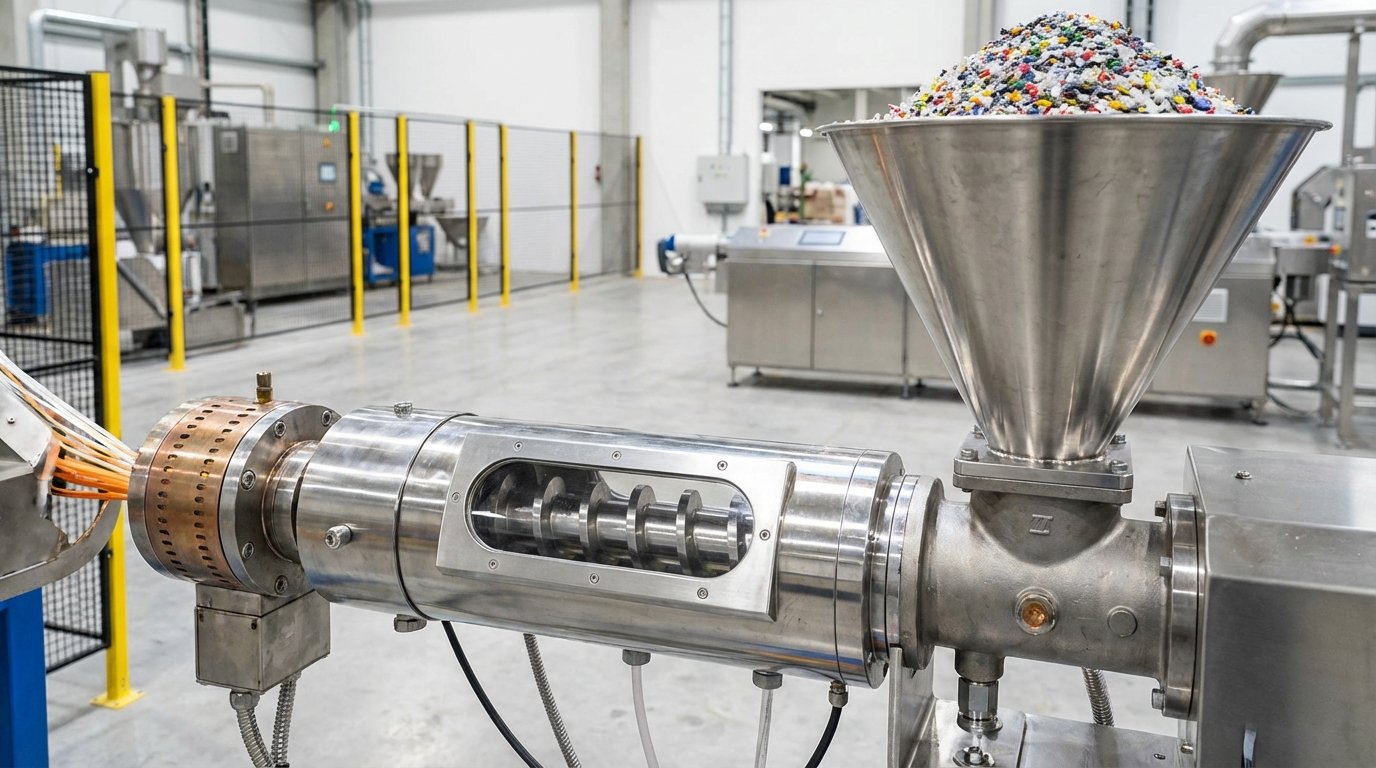
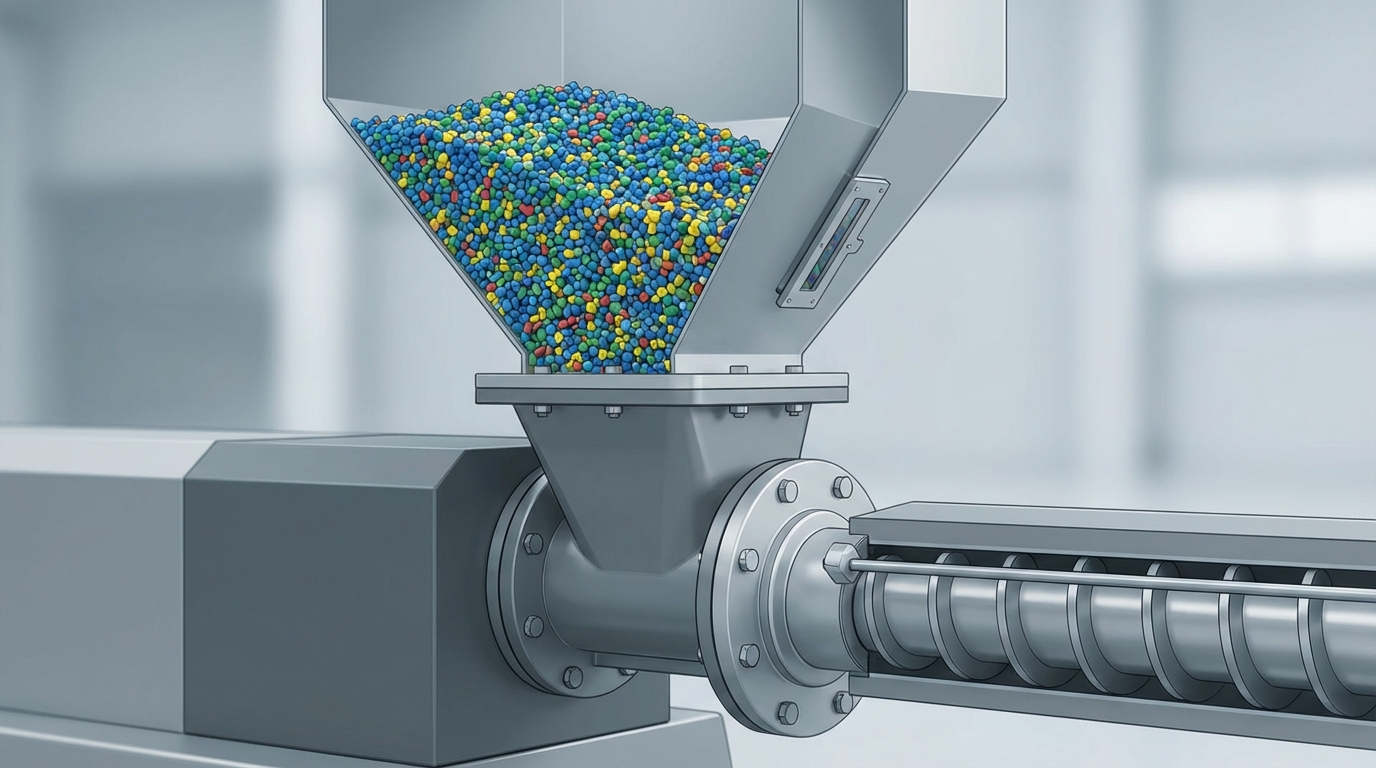
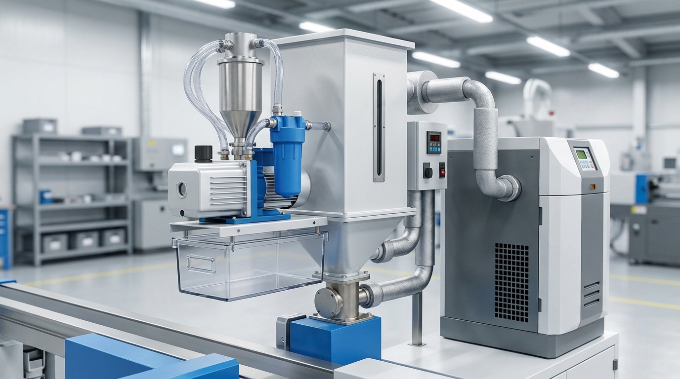
The hopper sits on top of the extruder barrel, right at the feed throat. It’s the funnel-shaped container where you dump your raw material—virgin pellets, recycled flakes, regrinds, or whatever you’re processing. Seems straightforward, right? Just a metal funnel.
It’s not that simple.
The hopper’s job is to deliver a consistent, uninterrupted flow of material into the screw’s feed zone. The moment that flow becomes inconsistent—bridging, ratholing, or surging—your output goes sideways. I’ve seen operators blame the screw, the die, even the resin supplier, when the real culprit was a poorly designed hopper that let material bridge across the throat opening.
There are two primary hopper feeding designs:
One detail most people overlook: the feed throat itself. It’s the transition between the hopper and the barrel, and it’s almost always water-cooled. Why? Because if heat migrates back from the barrel into the feed throat, pellets start softening and sticking together before the screw can grab them. That creates a plug. Production stops. Everyone panics.
Keep that cooling water flowing. Check the temperature regularly. It’s a $0 fix that prevents a $5,000 problem.
The hopper itself is just a container. What makes it actually useful in a production environment are the accessories bolted onto it. Skip these, and you’re asking for contamination issues, moisture defects, and manual labor you don’t need.
Magnetic traps are the cheapest insurance policy in extrusion. A magnetic grate or drawer magnet sits inside the hopper and catches ferrous metal contaminants—bits of wire, screws, staples, whatever got mixed into your recycled feedstock. One small piece of metal hitting your screw flights can score the barrel, damage the screw, or punch through a screen pack. I’ve pulled everything from roofing nails to paper clips out of hopper magnets on recycling lines. The magnet costs maybe $200. The screw repair costs $8,000.
Vacuum loaders automate the feeding process. Instead of an operator manually dumping bags of resin into the hopper every 20 minutes, a vacuum conveyor pulls material from a storage silo or gaylord directly into the hopper on demand. This isn’t a luxury—it’s a throughput multiplier. It also keeps the hopper lid closed, which reduces dust contamination and moisture absorption.
Hopper dryers are critical for hygroscopic materials like PET, nylon, and polycarbonate. These resins absorb atmospheric moisture, and if you extrude them wet, you get splay marks, bubbles, and degraded mechanical properties. A desiccant hopper dryer circulates hot, dry air through the material for 2-6 hours (depending on the resin) before it enters the screw. For PET recycling specifically, drying to below 50 ppm moisture content is non-negotiable—anything above that and you’ll see viscosity drop and haze in your pellets.
Even for polyolefins like PE and PP, which aren’t technically hygroscopic, surface moisture from washing lines can cause problems. A hot-air hopper dryer or even a simple heated hopper can make a noticeable difference in pellet quality when you’re running washed recycled film flakes.
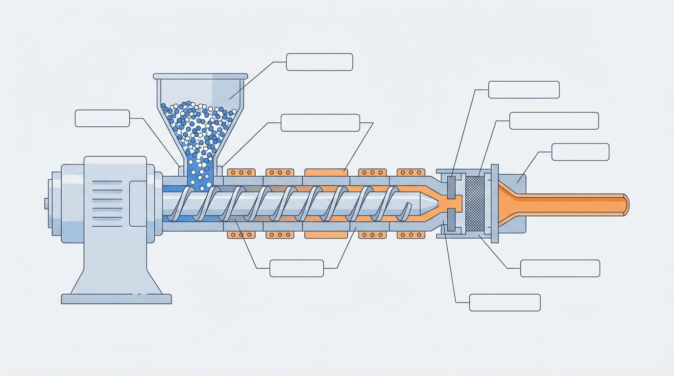
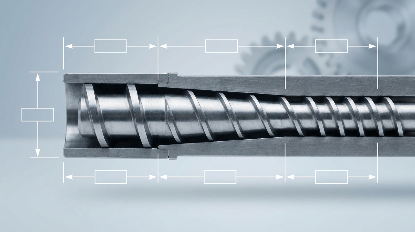
If the extruder has a soul, it’s the screw. This single rotating component does three jobs simultaneously: it conveys the solid material forward, melts it through shear and conducted heat, and meters the molten polymer at a consistent rate toward the die. Get the screw design wrong, and nothing downstream can fix it.
A standard single-screw has three distinct zones, each with a specific function:
This is the section directly under the hopper. The flight depth (the channel between the root of the screw and the barrel wall) is deepest here. Why? Because solid pellets have a low bulk density—they need room. The feed zone’s job is to grab solid material and push it forward. The channel is deep, the compression is minimal, and the material is still mostly solid.
A common rookie mistake: assuming a longer feed zone means more output. Not necessarily. Too long a feed zone on a recycling extruder processing pre-melted flakes can actually reduce efficiency because the material doesn’t need as much conveying distance.
Here’s where the magic happens. The flight depth gradually decreases, compressing the material. This compression does two things: it squeezes out trapped air (which would otherwise cause bubbles in your product), and it increases shear heating. The polymer transitions from solid to melt in this zone. The compression ratio—the ratio of feed zone channel depth to metering zone channel depth—typically ranges from 2:1 to 4:1 depending on the polymer.
For LDPE film recycling, I usually see compression ratios around 3:1 to 3.5:1. For rigid HDPE or PP, something closer to 2.5:1 works better. Get this wrong and you’ll either starve the metering zone or create so much shear that you degrade the polymer.
The shallowest section. By this point, the material should be fully melted. The metering zone’s job is to deliver a homogeneous melt at consistent pressure and temperature to the die. Flight depth is constant here, and any remaining unmelted particles (called “unmelt” or “gels”) are a sign that something upstream went wrong—either the compression ratio is off, the barrel temperatures are too low, or the screw speed is too high for the material to fully melt.
Two critical screw parameters you need to understand:
Some specialized screws add mixing elements—barrier flights, Maddock mixers, or pin mixing sections—to improve melt homogeneity. These are particularly valuable when processing recycled plastic into pellets, where feedstock consistency is never as good as virgin resin.
This is probably the question I get asked most at trade shows: “Should I go single-screw or twin-screw?”
My honest answer? It depends entirely on what you’re trying to do. And most people asking the question would be perfectly fine with a single-screw.
| Característica | Extrusora monohusillo | Extrusora de doble husillo |
|---|---|---|
| Mixing capability | Moderate (relies on screw design) | Excellent (intermeshing action) |
| Self-cleaning | No | Yes (co-rotating designs) |
| Material flexibility | Best for consistent feedstock | Handles variable/contaminated feed |
| Capital cost | Lower (30-50% less) | Más alto |
| Maintenance complexity | Simpler | More complex (two screws, tighter tolerances) |
| Typical applications | Film, pipe, profile, sheet extrusion | Compounding, filled materials, reactive extrusion |
| Throughput range | 50-2,000+ kg/hr | 20-5,000+ kg/hr |
Extrusoras monohusillo are the workhorses of the plastics industry. They’re simpler, cheaper, and perfectly adequate for straightforward melting and forming operations. If you’re running a standard extrusion line producing pipe, film, or profiles from relatively clean feedstock, a single-screw is your best bet.
Extrusoras de doble husillo shine when mixing is critical. Compounding color concentrates, blending additives into a base resin, processing heavily filled materials (like 40% glass-fiber-reinforced nylon), or handling reactive extrusion—these are twin-screw territory. The intermeshing screw design provides positive displacement and self-wiping action, which means better mixing and less material degradation.
Here’s the nuance most guides miss: in recycling applications, the choice isn’t always clear-cut. A single-screw extruder with a good mixing section handles most PE and PP recycling just fine. But if you’re dealing with mixed-polymer waste streams, heavy contamination, or need to compound recycled resin with virgin material and additives, a co-rotating twin-screw gives you the process flexibility to handle it.
One more thing—twin-screw extruders also come in co-rotating and counter-rotating configurations. Co-rotating is dominant for compounding. Counter-rotating is used more for PVC profile extrusion, where gentler shear is needed to avoid thermal degradation. Don’t mix them up.
The barrel is the cylindrical housing that surrounds the screw. Think of it as the oven that the screw works inside. But unlike a kitchen oven, the barrel doesn’t just add heat—it also needs to remove it in certain zones. Temperature control along the barrel is a balancing act between external heating, frictional (shear) heat generated by the screw, and active cooling.
A typical barrel is divided into 3-7 independent heating zones, each with its own temperature setpoint. The feed zone runs coolest (sometimes barely above ambient if the material is easy to convey). Temperatures increase through the compression zone and peak somewhere in the metering zone or at the die adapter.
For example, a typical temperature profile for recycled HDPE might look like:
But here’s what trips people up: those are setpoints, not actual melt temperatures. The real melt temperature is usually 10-30 C higher than the barrel setpoint because of shear heating from the screw. This is why you need a melt thermocouple at the die end—relying on barrel zone temperatures alone is like judging how well-done your steak is by looking at the oven thermometer instead of using a meat probe.
Heating methods in 2026 barrel designs include:
Cooling is equally important. When shear heating pushes a zone above its setpoint, air-cooling fans (or less commonly, water-cooled jackets) kick in. Without adequate cooling, you lose temperature control, and the melt degrades. I’ve seen operators disable cooling fans to “save energy” and then wonder why their product turned yellow. Don’t do that.
This is a topic that doesn’t get enough attention until something goes expensively wrong.
The inside surface of the barrel takes an absolute beating. Abrasive fillers, glass fibers, mineral-filled compounds, and even recycled resins containing trace contaminants all wear down the barrel bore over time. When the clearance between the screw flights and the barrel wall increases beyond about 0.1-0.15 mm per side (depending on screw diameter), you start losing output, melt quality, and energy efficiency.
In 2026, with the push toward processing more recycled content—which often contains sand, paper fibers, metal traces, and other abrasives—barrel wear has become a bigger issue than ever.
The main barrel liner technologies:
A practical tip from the field: if you’re running a recycling line processing washed post-consumer flakes, invest in bimetallic barrels from day one. I’ve seen operators try to save money with nitrided barrels on recycling extruders and end up replacing them within 12-18 months. The bimetallic barrel costs maybe 40% more upfront but lasts 3-4 years under the same conditions. The math isn’t even close.
Also worth noting: barrel wear isn’t uniform. The compression zone and the area around the screen changer see the most wear because that’s where pressure and abrasion are highest. Some manufacturers now offer barrels with different liner alloys in different zones—harder alloys where wear is worst, standard alloys where it’s lighter. Smart engineering.
Sitting between the end of the screw and the die is a component that most people underestimate: the breaker plate. It’s a thick metal disc with dozens of holes drilled through it, and it holds a stack of wire mesh screens (the screen pack) against the melt flow.
The breaker plate and screen pack serve three critical functions:
Filtration. The screen pack catches unmelted particles, degraded polymer chunks, and foreign contaminants before they reach the die. In recycling, this is absolutely essential. Even well-washed post-consumer plastic contains residual contaminants—paper fibers, wood particles, bits of label adhesive, tiny metal fragments that got past the hopper magnet. Without screen filtration, these contaminants end up in your product.
Back pressure generation. The restriction created by the screens and breaker plate forces the melt to work harder to pass through, building pressure in the metering zone. This back pressure is crucial for complete melting and melt homogeneity. Too little back pressure (screens too coarse or too few) means unmelted particles get through. Too much (screens too fine or too many layers) means excessive pressure, reduced throughput, and potential overheating.
Flow conversion. The rotational motion imparted by the screw gets converted to linear, axial flow as the melt passes through the breaker plate holes. Without this, the melt would enter the die with a spiraling motion, causing visible swirl marks in the product.
A typical screen pack for recycling might use a combination like: 20 mesh / 60 mesh / 100 mesh / 60 mesh / 20 mesh (coarse-to-fine-to-coarse sandwich). The coarse outer screens provide structural support for the fine inner screens.
For continuous production, hydraulic screen changers allow you to swap dirty screens for clean ones without stopping the extruder. There are slide-plate types, rotary types, and continuous belt types. On a busy recycling line running contaminated feedstock, a continuous screen changer isn’t a luxury—it’s a necessity. Manual screen changes on a heavily contaminated line might be needed every 2-4 hours, which means shutting down, purging, opening the head, swapping screens, and restarting. A continuous screen changer eliminates all that downtime.
The die is where everything comes together—literally. All the work done by the hopper, screw, barrel, and screen pack culminates here. The die shapes the molten polymer into its final cross-sectional geometry as it exits the extruder.
Think of the die as a precision-machined nozzle. The internal flow channels guide the melt from a round barrel exit into whatever shape you need: a flat sheet, a round pipe, a thin film, or a complex window profile. The die doesn’t just shape the plastic—it determines the dimensional accuracy, surface finish, and uniformity of your product.
Key die design principles:
Uniform flow distribution. The melt must exit the die at the same velocity across the entire cross-section. If the center flows faster than the edges (or vice versa), you get thickness variations. Die designers use coat-hanger manifolds, flow restrictors, and choker bars to balance the flow. This is part science, part art—and experienced die designers are worth their weight in gold.
Proper land length. The “land” is the final parallel section of the die channel before the melt exits. It stabilizes the flow and allows the melt to “relax” from the stresses of being squeezed through the die. Too short a land gives unstable output. Too long increases pressure drop and can cause excessive shear heating. Typical land lengths are 10-20 times the die gap.
Temperature control. Most dies have their own heating zones—cartridge heaters or band heaters that maintain the die body at a uniform temperature. Cold spots in the die cause flow hesitation and visible lines in the product. Hot spots cause localized thinning.
Die swell. When the melt exits the die, it expands because the elastic stresses stored during flow through the die are released. This “die swell” can increase the extrudate dimensions by 10-30% beyond the die opening size. Die designers account for this, but it’s also affected by melt temperature, extrusion speed, and polymer type. It’s one of those variables that keeps extrusion engineers humble.
Understanding how the die works is essential for anyone involved in the plastic extrusion process, because die adjustments are often the first thing operators reach for when product dimensions drift—even when the root cause is actually upstream.
Not all dies are created equal. The die you need depends entirely on what you’re making. Here’s a breakdown of the most common configurations:
Used for sheet, flat film, and coating applications. The melt enters from a round adapter and spreads out through a coat-hanger-shaped manifold into a wide, thin slot. Lip gap is adjustable—usually with a row of bolts across the width that let you fine-tune the thickness profile. Widths range from 300 mm for lab dies to over 3,000 mm for production sheet lines.
The critical spec here is lip gap uniformity. On a 2-meter-wide sheet die, a variation of just 0.05 mm across the lip can create visible thickness bands in the product. Modern flat dies in 2026 use automatic lip adjustment systems with thickness gauges providing real-time feedback.
Used for blown film, pipe, and tubing. The melt flows around a central mandrel and exits through an annular (ring-shaped) gap. For blown film, the extrudate is then inflated with air to create a bubble. For pipe, it passes through a sizing sleeve and vacuum tank.
Annular dies have their own set of challenges. Weld lines (also called spider lines or knit lines) form where the melt stream splits around the mandrel supports and then rejoins. Spiral mandrel designs minimize these by forcing the melt through a helical path that redistributes the flow before it reaches the exit.
The most complex category. These produce non-circular, non-flat shapes—window frames, deck boards, automotive trim, cable channels, you name it. Every profile die is essentially custom-designed for the specific product geometry.
Profile die design requires accounting for differential die swell (different wall thicknesses swell at different rates), cooling shrinkage, and the tendency of asymmetric shapes to warp. It’s common for a new profile die to go through 3-5 design iterations before it produces acceptable parts. This is why profile dies are expensive—$5,000 to $50,000+ depending on complexity.
For recycling operations, the die often takes the form of a multi-hole strand die or an underwater pelletizing die plate. Strand dies push the melt through dozens of small holes, forming spaghetti-like strands that are cooled in a water bath and chopped into pellets. Underwater pelletizing dies cut the strands immediately at the die face, producing uniform spherical pellets. The choice between them affects pellet shape, cooling efficiency, and throughput.
The drive system is the muscle behind the screw. It consists of three main components: the electric motor, the gearbox (reducer), and the speed control system. Together, they determine how fast the screw turns and how much torque it delivers.
The motor needs to deliver enough torque to rotate the screw against the resistance of compressing and shearing molten polymer—which is considerable. A 90mm single-screw extruder processing HDPE might need a 75-110 kW motor. Scale up to a 150mm screw for high-throughput recycling, and you’re looking at 200-350 kW.
AC motors with variable-frequency drives (VFDs) have completely replaced the old DC motor setups in 2026. And honestly, good riddance. DC motors required brush maintenance, had limited speed ranges, and were energy hogs at partial loads. A modern VFD-controlled AC motor gives you:
En caja de cambios sits between the motor and the screw. Its job is to reduce the motor’s high RPM to the lower RPM the screw needs while multiplying torque. A typical reduction ratio is 15:1 to 20:1. So a motor spinning at 1,500 RPM drives the screw at 75-100 RPM, but with 15-20 times the torque.
Here’s something I wish more operators understood: the gearbox is often the most expensive single component in the drive train. A gearbox failure can cost $20,000-$50,000 to replace and take weeks to deliver. Yet I regularly see gearboxes running with old oil, improper oil levels, or no temperature monitoring whatsoever. Check your gearbox oil level weekly. Change the oil at the manufacturer’s recommended interval—usually every 5,000-8,000 operating hours. Monitor the oil temperature. If it’s running hotter than normal, something is wearing out inside.
En thrust bearing assembly—often integrated into the gearbox—deserves special mention. It absorbs the enormous axial force generated by the screw pushing melt forward against the die resistance. On a large extruder, this thrust load can exceed 50 tons. Thrust bearing failure is catastrophic and almost always preventable with proper lubrication and monitoring.
I once walked into a facility where the operator was running a recycling extruder using nothing but the barrel temperature displays and his gut feeling. No melt pressure reading. No melt temperature sensor. No amperage monitoring. He’d been doing it for years and thought everything was fine.
It wasn’t. His scrap rate was 12%. Industry average for that application was under 3%.
The control panel is the brain of the extruder, and the sensors are its nervous system. Without accurate, real-time data, you’re flying blind. Here’s what a properly instrumented extruder should be monitoring:
Barrel thermocouples (typically J-type or K-type) are embedded in each heating zone to measure barrel wall temperature. These feed back to the temperature controllers, which cycle the heaters and cooling fans to maintain setpoints. But remember—barrel temperature is not melt temperature.
Melt thermocouples are inserted through the barrel wall so the tip protrudes into the melt stream, usually near the die adapter. This gives you the actual temperature of the polymer. The difference between barrel setpoint and actual melt temperature can be 20-40 degrees Celsius, and that gap changes with screw speed, material, and throughput. If you only have one melt thermocouple on your extruder, put it here.
Melt pressure sensors (typically strain-gauge or piezoelectric type) are mounted at the end of the barrel, before the breaker plate, and sometimes after the screen pack. They tell you:
A sudden pressure spike can indicate a blockage or contamination event. A gradual rise means your screens are loading up with contaminants and need changing. Pressure data is your early warning system—ignore it at your peril.
Modern extruders use a Programmable Logic Controller (PLC) to coordinate all the control loops—temperature, pressure, screw speed, feeder speed—and a Human-Machine Interface (HMI) touchscreen that lets operators visualize and adjust everything. Good HMI software logs historical data, displays trend graphs, and triggers alarms when parameters drift outside acceptable ranges.
In 2026, more extruder manufacturers are integrating IoT connectivity and cloud-based monitoring. This means you can check your extruder’s status from your phone, receive alerts when a heater fails at 2 AM, and analyze production data trends over months to predict maintenance needs before failures occur. According to Plastics Today, over 40% of new industrial extruders shipped in 2025 included some form of remote monitoring capability, and that number is climbing fast.
Understanding each part individually is necessary. But the real skill—the thing that separates experienced operators from beginners—is understanding how all these components interact as a system. When a defect shows up in your product, the cause is almost never a single component acting alone. It’s a chain reaction.
Let me walk you through some common defects and the component interactions behind them:
The extrudate thickness pulses rhythmically. Most people immediately blame the screw. But surging is usually a feeding problem. Inconsistent material flow from the hopper (bridging, or a partially blocked feed throat) causes the screw to alternately starve and flood. The result is cyclic pressure variation at the die.
Fix: Check the hopper and feed throat first. Is the feed throat cooling water running? Is the material bridging? Is the crammer feeder (if present) operating consistently? Only after eliminating feeding issues should you look at screw wear or temperature profile problems.
The extrudate surface looks rough, wavy, or “sharkskin”-textured. This happens when the melt is forced through the die at a shear rate that exceeds the polymer’s critical shear stress. It’s a die problem and a temperature problem working together.
Fixes: Raise the die temperature (reduces melt viscosity, reduces shear stress). Reduce extrusion rate. Increase the die land length. Use a die with a larger gap. Some operators add a small amount of processing aid (fluoropolymer additive) to the resin—it migrates to the die surface and acts as a lubricant.
Tiny dark particles in the extrudate. This is degraded polymer—material that sat too long in a dead spot at high temperature and carbonized. The culprits are usually dead zones in the die, a poorly designed adapter between the barrel and die, or old degraded material stuck in the screen changer.
This is particularly common after material changes or color changes. A thorough purge between runs is essential. And if your die has known dead spots (ask the manufacturer), consider redesigning the flow channels or at minimum doing a regular die teardown and cleaning.
Small bubbles or streaky surface defects. The material went into the extruder wet. The hopper dryer failed, wasn’t set to the right temperature, or the material didn’t have enough residence time in the dryer. For hygroscopic resins like PET and nylon, this is the number one quality issue.
For recycling operations processing washed flakes, residual surface moisture is a constant battle. Mechanical dewatering and thermal drying before the extruder are critical—which is why a proper plastic washing and drying line upstream of the extruder matters so much.
Visible lines running along the extrusion direction on the product surface. These are caused by scratches, nicks, or buildup on the die lip. Even a tiny imperfection of 0.01 mm on the die lip surface will telegraph as a visible line on the product. Regular die lip cleaning and polishing is essential. Handle die components with care—a dropped die lip is an expensive mistake.
I’ll be blunt: most extruder breakdowns I’ve seen in the field were preventable. Not with expensive upgrades or fancy technology—just with basic, consistent maintenance that someone decided to skip because production was “too busy to stop.”
Here’s a practical maintenance framework that actually works:
One more tip that’s saved me more than once: keep a spare screw. A screw rebuild takes 4-8 weeks. If your only screw fails or wears out, your line is down for that entire period. Having a spare screw—even a rebuilt one—means you can swap and keep running while the worn one gets repaired. For a high-throughput recycling line producing $10,000-$20,000 of product per day, the cost of a spare screw pays for itself the first time you need it.
The screw. Full stop. Every other component supports the screw’s function. A perfectly maintained barrel, die, and control system can’t compensate for a badly designed or worn-out screw. The screw determines melting efficiency, mixing quality, output rate, and melt homogeneity. If your budget only allows upgrading one component, upgrade the screw.
It depends on the material being processed. Running unfilled polyolefins on a nitrided screw, you might get 5-8 years before wear becomes critical. Processing glass-fiber-filled materials or abrasive recycled feedstock, a standard screw might last only 12-24 months. The key is measuring—don’t guess. Track flight diameter measurements quarterly and replace or rebuild when clearance exceeds the manufacturer’s tolerance, typically when the screw OD is worn down by 0.2-0.3 mm from nominal.
The most common causes, in order of frequency from my experience:
Start troubleshooting at the hopper and work forward. The problem is usually simpler than you think.
Absolutely, and it’s often the smartest investment you can make. Common upgrades include:
You don’t need to buy a new extruder to get new-extruder performance. Targeted upgrades to the right components can boost throughput by 15-25% and reduce scrap by half.
A plasticizing extruder’s primary job is to melt and homogenize the polymer. A forming extruder shapes the melt into a specific product geometry through the die. In many setups—especially recycling lines—these are the same machine. But in tandem extrusion systems, one extruder melts and a second extruder (or gear pump) meters the melt to the die, separating the two functions for better control.
Higher screw speed increases throughput but also increases shear heating, reduces residence time, and can cause incomplete melting if pushed too far. There’s always a sweet spot. For most recycling applications, I find the optimal range is 60-80% of the screw’s maximum rated RPM. Going above that usually gains marginal throughput at the cost of significant quality degradation. Below 40%, you risk insufficient shear for proper melting. Find the sweet spot for your specific material and die combination, and document it.
Every component in a plastic extruder machine exists for a reason, and they all affect each other. The hopper feeds the screw. The screw melts and pumps within the barrel. The breaker plate and screens filter and build pressure. The die shapes the final product. The drive system provides power. The control system ties everything together with data.
When one part underperforms—whether from wear, poor design, or neglected maintenance—the effects cascade through the entire system. That’s why understanding the function of each component isn’t just academic knowledge. It’s the foundation for troubleshooting faster, maintaining smarter, and producing better.
After a decade of working with these machines across dozens of facilities, here’s what I know for certain: the operators and engineers who understand their extruder at the component level consistently outperform those who treat it as a black box. They catch problems earlier, make better purchasing decisions, and waste less material and money.
If you’re setting up or optimizing a plastic recycling line and need guidance on selecting the right extruder configuration for your specific material stream, explore JianTai’s recycling equipment solutions or reach out to their technical team for a consultation tailored to your production goals.