Realiza algunos cambios en el entorno mundial
La máquina que ha comprado le reportará beneficios, pero también cambiará indirectamente el medio ambiente mundial y dará a los residuos plásticos una oportunidad de aprovechamiento.

Realiza algunos cambios en el entorno mundial
Last summer, I spent three days on the floor of a plastics factory in Guangdong watching a single-screw extruder churn out 400 kg of HDPE pipe per hour. The operator, a guy with 22 years on the job, told me something that stuck: “Everyone thinks extrusion is just melting plastic and pushing it through a hole. They’re wrong. It’s a chemistry experiment happening at 200 degrees, and you get one shot to control it.” He was right. The proceso de extrusión de plásticos is the continuous conversion of raw polymer — usually pellets or flakes — into a uniform cross-section profile by forcing melted material through a shaped die. It accounts for roughly 36% of all plastic processing worldwide, and yet most explanations online barely scratch the surface.
This guide breaks down every phase of the plastic extrusion process step by step, from raw material handling to the final cut. Whether you’re an engineer specifying a new line, a procurement manager evaluating equipment, or a student trying to understand polymer processing, you’ll walk away with a detailed, practical understanding — not textbook fluff.
Strip away all the jargon, and plastic extrusion is surprisingly straightforward in concept. You feed solid plastic into one end of a heated barrel, a rotating screw pushes it forward while melting and mixing it, and the molten polymer gets forced through a steel die that shapes it into a continuous profile — pipe, sheet, film, tubing, window frame, you name it. The profile then gets cooled, sized, and cut to length.
Simple concept. Brutal execution.
The reason I say that is because the gap between “understanding the idea” and “running a profitable extrusion line” is enormous. Temperature control across six or more barrel zones, screw design that balances shear heat with mixing efficiency, die swell compensation, haul-off speed synchronization — each variable interacts with every other one. Change your resin supplier and suddenly your melt flow index shifts by 0.3 g/10 min, and your dimensional tolerances go out the window. I’ve seen it happen more times than I can count.
Unlike injection molding (which is a batch process — fill, cool, eject, repeat), extrusion is continuous. The screw never stops turning. Material flows in one end and product emerges from the other, theoretically forever. This is what makes extrusion so economically powerful for high-volume production. A well-tuned pipe extrusion line can run 24/7 for weeks between shutdowns.
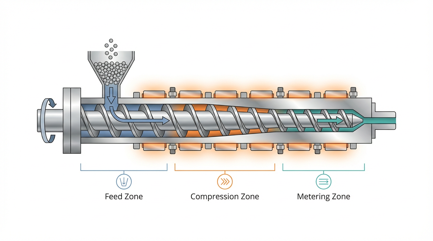
The fundamental physics involve three things happening simultaneously inside the barrel:
That three-zone model — feed, compression, metering — is the backbone of every single-screw extruder ever built. Twin-screw machines work differently (more on that in a moment), but the single-screw concept is where 80%+ of production extrusion happens.
Here’s something that took me years to fully appreciate: the majority of extrusion defects trace back to what happens before the plastic even enters the barrel.
Raw material prep involves:
If you’re working with recycled plastic feedstock, material preparation becomes even more critical. Contamination levels, mixed polymer content, and inconsistent melt flow indexes all compound the challenge.
The feed throat — that opening at the back of the barrel where pellets drop in — seems like the simplest part of the machine. It’s not.
The feed throat is typically water-cooled (or air-cooled on smaller machines) to prevent pellets from melting prematurely and forming a bridge that blocks material flow. This is called bridging, and it’s one of the most annoying problems in extrusion because it causes surging — periodic fluctuations in output that show up as thickness variations in your product.
Flood feeding (gravity feeding) is the standard approach for single-screw extruders: you keep the hopper full and the screw takes what it can grab. The screw speed determines throughput. Starve feeding, where a metering device controls the feed rate independently of screw speed, is more common on twin-screw extruders and gives you an extra degree of process control.
This is where the magic happens. Or the disaster, depending on your setup.
A standard single-screw extruder barrel is a nitrided steel cylinder with electric heater bands wrapped around it, divided into multiple temperature zones (typically 4-8 zones depending on L/D ratio). The screw itself is the most engineered component in the entire system — its geometry dictates melting efficiency, mixing quality, and output stability.
Key screw parameters:
| Parámetro | Typical Range | Why It Matters |
|---|---|---|
| L/D Ratio (length to diameter) | 24:1 to 36:1 | Longer screws = more melting/mixing time. 30:1 is the sweet spot for most applications. |
| Compression Ratio | 2:1 to 4:1 | Ratio of feed zone channel depth to metering zone depth. Higher = more shear. PE typically needs 3:1 to 3.5:1. |
| Flight Depth (feed zone) | Varies by diameter | Deeper channels = higher throughput but potentially less melting efficiency. |
| Screw Speed | 20-150 RPM (single-screw) | Faster = more output + more shear heat. Too fast and you degrade the polymer. |
One thing most guides won’t tell you: screw design is not universal. A screw optimized for LDPE film extrusion will perform terribly with rigid PVC. PVC is heat-sensitive and needs low shear; LDPE needs aggressive melting action. I’ve consulted for companies that bought a used extruder, tried to run a different resin on the existing screw, and couldn’t figure out why they were getting unmelts and gels. The answer was always the screw.
Barrier screws (Maddock, Maillefer designs) are now standard on most modern extruders. They use a secondary flight to separate the solid bed from the melt pool, dramatically improving melting consistency compared to conventional single-flight screws. If you’re buying new equipment in 2026, don’t accept a conventional screw design — barrier screws are the minimum baseline.
As the screw pushes pellets forward, the channel depth decreases. This compression forces the material against the hot barrel wall, where a thin melt film forms. The solid bed gets progressively smaller as it moves down the barrel, and ideally, by the time material reaches the metering zone, it’s 100% molten and homogeneous.
“Ideally” is doing a lot of heavy lifting in that sentence.
In reality, achieving complete melting is one of the biggest challenges in extrusion. Unmelted particles (called “unmelts” or “gels” depending on who you ask) are a constant battle, especially at high throughput rates. The industry rule of thumb: about 70-80% of the energy needed to melt the plastic comes from shear friction generated by the screw, not from the barrel heaters. The heaters mainly provide supplemental heat and maintain temperature stability. This is why screw speed has such a dramatic effect on melt temperature — and why running too fast can cause thermal degradation.
According to research published by the Society of Plastics Engineers (SPE), melt temperature uniformity within +/- 2 degrees C across the melt stream cross-section is achievable with properly designed barrier screws and static mixers, but many production lines operate with +/- 5-10 degrees C variation without realizing it.
Mixing elements — either built into the screw tip (distributive mixers like pineapple mixers, or dispersive mixers like Maddock sections) or as separate static mixer units between the screw tip and the die — help homogenize the melt. For color-critical applications, I always recommend a static mixer. They add minimal pressure drop and dramatically improve color distribution.
Between the screw tip and the die sits the breaker plate — a thick steel disc with dozens of small holes — backed by one or more wire mesh screens (the screen pack). This assembly serves three purposes:
Screen mesh sizes typically range from 20 mesh (coarse, for filled compounds) to 200 mesh (fine, for optical-quality film). A common configuration is a 20/60/100/60/20 mesh stack. When processing recycled materials, continuous screen changers — either slide plate or rotary disc types — are essential because contamination levels clog screens much faster than virgin resin does.
Here’s a practical tip from years of troubleshooting: if you’re seeing periodic pressure fluctuations at the die, check your screen pack first. A partially blocked screen creates uneven flow resistance and is one of the most common — and most overlooked — causes of dimensional variation in extruded products.
The die is the final shaping tool. Molten polymer enters as a round stream from the adapter and gets redistributed into whatever cross-section you need — flat sheet, annular pipe, complex window profile, thin film.
Common die types:
Die design is where art meets engineering. The challenge is ensuring uniform melt velocity across the entire die exit. If one side flows faster than the other, you get thickness variation, warpage, or internal stresses in the final product. Computational fluid dynamics (CFD) simulation has become standard for die design in 2026, but even with simulation, most dies require 2-3 iterations of trial and adjustment before they produce acceptable product.
Something I tell every client: never cheap out on the die. A $3,000 die on a $150,000 extrusion line will cost you $30,000 in scrap and downtime trying to make it work. The die is the most cost-sensitive component relative to its price.
When polymer exits the die, it swells. The extrudate comes out bigger than the die opening — sometimes 10-30% bigger, depending on the material, shear rate, and melt temperature. This is called die swell (or extrudate swell), and it happens because the polymer chains, which were stretched and aligned by shear flow inside the die, relax and spring back to a more random configuration once the constraining walls are gone.
Die swell is not a defect. It’s physics. But if you don’t account for it in your die design, your product dimensions will be wrong. High molecular weight polymers swell more. Higher shear rates (faster extrusion speeds) cause more swell. Higher melt temperatures reduce swell slightly.
This is one of those things where experience matters enormously. A veteran die designer can look at a resin data sheet and estimate die swell within a few percent. A newcomer will be chasing dimensions for days.
Once the molten profile exits the die, it needs to be cooled and solidified while maintaining precise dimensions. This is the calibration stage, and it’s arguably as important as the die itself.
Cooling methods vary by product type:
Cooling rate directly affects material properties. Cool too fast and you build in internal stresses that cause warpage or cracking later. Cool too slow and your production rate drops, plus crystalline polymers (HDPE, PP) may develop excessive crystallinity that makes the product brittle. For PE pipe, the ISO 4427 standard specifies minimum cooling requirements precisely because of this relationship between cooling rate and long-term performance.
A haul-off unit — typically a caterpillar puller with rubber belts or a set of driven rolls — grips the cooled extrudate and pulls it away from the die at a controlled, constant speed. This is a deceptively critical piece of equipment.
The haul-off speed relative to the extrusion rate determines:
Modern haul-off units use servo drives with closed-loop feedback from downstream measurement systems (laser micrometers, ultrasonic wall thickness gauges). The best systems maintain speed stability within +/- 0.1%. That might sound like overkill, but on a medical tubing line where the tolerance is +/- 0.05 mm on a 2 mm wall, it’s absolutely necessary.
The last station on the extrusion line is the cutter. For pipe and profiles, this is typically a traveling saw or knife that moves with the product and cuts without stopping the line. For sheet, a guillotine shear. For pelletizing applications (where the extruder is making gránulos de plástico rather than finished profiles), a strand pelletizer or underwater pelletizer dices the extrudate into uniform granules.
Cut quality matters more than people realize. A rough cut on a PVC window profile means extra finishing work. A poorly timed cut on a pipe line means scrap. Planetary saws with carbide-tipped blades are the standard for clean, chip-free cuts on rigid profiles.
After cutting, products may go through additional finishing steps: printing, punching, belling (for pipe sockets), coiling (for flexible tubing), or stacking and packaging. These are downstream operations that vary widely by application.
I get asked this question constantly, so let me give you a clear answer.
Extrusoras monohusillo are the workhorse for most profile, pipe, sheet, and film extrusion. They’re simpler, cheaper, and perfectly adequate when you’re processing a single, pre-compounded resin. About 85% of extrusion lines worldwide use single-screw machines.
Extrusoras de doble husillo (co-rotating or counter-rotating) excel at compounding — mixing polymers with fillers, additives, and other polymers. They offer superior mixing, precise temperature control, and the ability to feed multiple ingredients at different points along the barrel. If you’re making masterbatch, compounding wood-plastic composites, or processing PVC (which is almost always processed on counter-rotating twin-screws for dry-blend feeding), twin-screw is the right choice.
The mistake I see? Companies buying twin-screw extruders for straightforward pipe or profile extrusion because someone told them twin-screw is “better.” It’s not better — it’s different. And it costs 2-3x more for the same throughput. Don’t overspend on capability you don’t need.
This is the section I wish someone had given me when I started. Every extrusion defect has a cause, and most causes are fixable once you know where to look.
| Defect | Appearance | Most Likely Causes |
|---|---|---|
| Shark skin (melt fracture) | Rough, ridged surface | Shear stress at die lip exceeds critical value. Reduce extrusion rate, increase melt temp, or use a processing aid. |
| Surging | Periodic thickness variation | Inconsistent feeding (bridging), worn screw/barrel, or fluctuating back pressure from clogged screens. |
| Gels / Unmelts | Small lumps or clear spots in the product | Insufficient melting — screw design issue, too high throughput, or degraded material from dead spots. |
| Die lines | Longitudinal streaks on the surface | Damage or buildup on the die lip. Clean or polish the die land. |
| Moisture splay | Silver streaks or bubbles | Wet resin. Dry it properly. No shortcut exists for this one. |
| Warpage | Product curves or twists after cooling | Uneven cooling, asymmetric die flow, or excessive orientation from drawdown. |
| Discoloration / Degradation | Yellow or brown streaks | Melt temperature too high, residence time too long, or dead spots in the flow path. |
If I could give one piece of advice to anyone running an extrusion line, it’s this: keep a logbook. Record every parameter change, every defect, every material lot number. When a problem recurs three months later, that logbook is worth its weight in gold. I’ve solved problems in 15 minutes using historical data that would have taken days of trial and error without it.
Not every plastic is equally suited to extrusion. Here’s a quick reference for the most common ones:
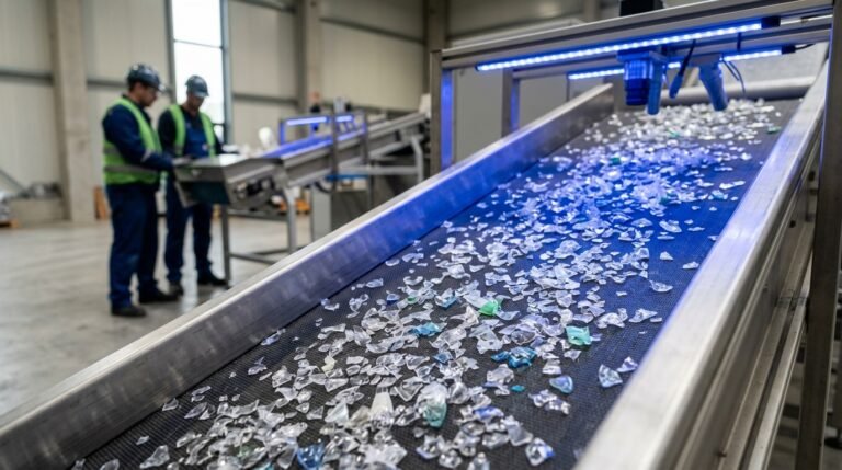
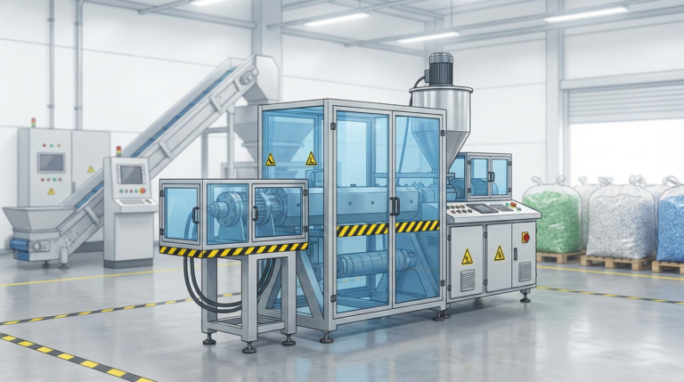
Here’s where things get interesting for 2026 and beyond. Extrusion isn’t just for making new products from virgin resin — it’s the core technology behind reciclaje de plásticos.
In a recycling context, the extruder serves as the re-melting and re-pelletizing machine. Washed, dried plastic flakes are fed into the extruder, melted, filtered through fine screens to remove contaminants, degassed (often with a vented barrel section or vacuum port), and then pelletized for resale as recycled resin.
The challenges are different from virgin extrusion. Recycled feedstock is inconsistent — variable melt flow, mixed polymer contamination, residual moisture, odors. This is why recycling extruders typically have:
Según el Association of Plastic Recyclers (APR), global demand for recycled polyethylene and polypropylene is projected to exceed 30 million metric tons annually by 2027, driven by brand owner commitments and extended producer responsibility legislation. That demand is creating a massive market for high-quality recycling extrusion lines.
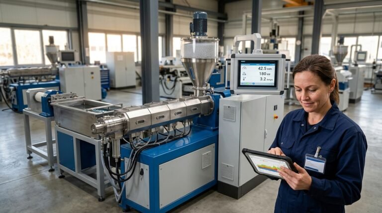
Running an extruder by feel and intuition worked in the 1990s. It doesn’t cut it anymore.
Modern extrusion lines use integrated control systems that monitor and adjust:
Industry 4.0 integration — where extruder data feeds into cloud-based analytics platforms for predictive maintenance and process optimization — is moving from “nice to have” to “standard expectation” in 2026. If your equipment supplier can’t offer this, they’re behind the curve.
Let me close with some hard-won lessons that you won’t find in any textbook:
“The best extruder operator I ever met checked three things before every shift: material moisture, screen pack condition, and die lip cleanliness. He had fewer quality complaints in a year than most operators have in a month.”
The plastic extrusion process is one of those technologies that rewards patience, precision, and continuous learning. Ten years in, I’m still picking up new tricks. If you’re just starting out, don’t get discouraged by the complexity — focus on understanding the fundamentals (material behavior, screw function, die flow, cooling dynamics), and the rest will follow.
It depends entirely on the polymer. LDPE extrudes at around 160-200 degrees C, HDPE at 180-230 degrees C, PP at 200-260 degrees C, and PVC at a much lower 150-185 degrees C because it degrades easily. Nylon runs hot at 230-290 degrees C. These are barrel set temperatures — actual melt temperatures will be higher due to shear heating.
Extrusion is a continuous process that produces products with a constant cross-section (pipe, sheet, profiles). Injection molding is a batch process that fills a closed mold cavity to produce discrete 3D parts (bottles, caps, housings). Different machines, different tooling, different economics. Extrusion wins on cost per kg for high-volume, constant-profile products. Injection molding wins for complex 3D geometries.
Line speed varies enormously by product. Thin-wall medical tubing might run at 100+ meters per minute. Large-diameter HDPE pipe (600 mm+) might crawl at 0.5-2 meters per minute. Blown film lines typically operate at 30-80 meters per minute. The limiting factor is almost always cooling — you can only run as fast as you can solidify the product.
Absolutely, and it’s becoming the norm rather than the exception. Recycled HDPE, LDPE, PP, and PET are all routinely extruded into new products. The key challenges are contamination removal, consistent melt flow properties, and odor control. Purpose-built recycling extrusion lines with enhanced filtration and degassing handle these challenges effectively.
L/D ratio is the length of the screw divided by its diameter. A 90 mm screw that is 2,700 mm long has a 30:1 L/D ratio. Higher L/D means more residence time in the barrel, which generally means better melting and mixing. Most general-purpose extruders use 24:1 to 30:1. Compounding and recycling applications often go to 34:1 or 36:1 for the extra mixing capability.
Start with your required output rate in kg/h, then work backward. A 60 mm single-screw extruder typically produces 40-80 kg/h of PE. A 90 mm machine does 150-300 kg/h. A 120 mm machine handles 300-600 kg/h. These are rough ranges — actual output depends on the resin, screw design, and product geometry. Always size slightly larger than your current need to leave room for growth. Buying an undersized extruder and running it at maximum capacity is a recipe for quality problems and premature wear.